Solenoid Valve Common Symbols
Safe area, ATEX hazardous area solenoid valves, process valves, angle seat piston valves, FRL's both standard and stainless steel, pressure reducing valves, pressure sustaining valves, pressure relief valves, pilot float valves, silent check valves, coaxial solenoid and pneumatic valves, 5/2 and 5/3 way pneumatic valves, filters, regulators and lubricators, foot suction hose strainers, pinch valves, actuated ball valves, solenoid magnets - coils and connectors.
2/2 Valve; 2 Ports, 2 Positions
3/2 Valve; 3 Ports, 2 Positions
4/2 Valve; 4 Ports, 2 Positions

4/3 Valve; 4 Ports, 3 Positions
5/2 Valve; 5 Ports, 2 Positions
5/3 Valve; 5 Ports, 3 Positions
Accumulator
Air Dryer
Air Motor (One Directional Flow)
Air Motor (Two Directional Flows)
Check Valve (Spring Loaded)
Compressor
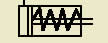
Cylinder -----(Spring Return)
Cylinder Double Acting (Double Rod)
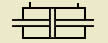
Cylinder Double Acting (Single Fixed Cushion)
Cylinder Double Acting (Two Adjustable Cushions)
Differential Pressure
Direction of Flow
Exhaust Line or Control Line
Filters and Regulators
Filter (Automatic Drain)
Filter (Manual Drain)
Fixed Restriction
Flexible Line
Flow Control Valve
Flow Gauge
Lever
Lines Connected
Lines Crossing
Lubricator
Muscular Control
One Bypass Flow Path and Two Closed Ports
One Flow Path
Pedal or Treadle
Pilot Pressure (External)
Pilot Pressure (Internal)
Plugged Port
Pneumatic
Pressure Actuated Electric Switch
Pressure Gauge
Pressure Regulator (Adjustable, Non-Relieving)

Pressure Regulator (Adjustable, Self-Relieving)
Push Button
Quick Acting Coupling
Roller
Roller (One-Way)
Shuttle Valve
Silencer
Single Square
Solenoid and Pilot Manual Override and Pilot
Solenoid (Single Winding)
Spring

Two Closed Ports
Two Distinct Positions and One Transitory (Center) Position
Two Flow Paths
Two Flow Paths and One Closed Port
Two Flow Paths with Cross Connection
Vacuum Pump
Variable Restriction
Working Line
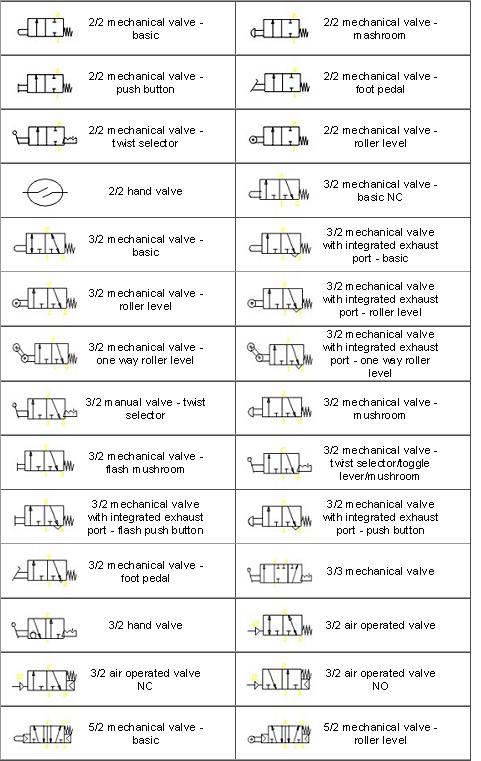
Mechanical valve symbols.
Symbols for different line types
The following symbols are generally in accordance with BS 1553-1 and BS 5070
Symbols for pipe supports.
Symbols for line fitting.
Symbols for Valves
Symbols for valve actuators
Symbols for instruments.
Symbols for flow instruments.
Instrument Identifier symbols.
| Measured Variable | Type of Conditioner | Type of Component |
|---|---|---|
| F = Flow | R = Recorder | T = Transmitter |
| L = Level | I = Indicator | M = Modifier |
| P = Pressure | C = Controller | E = Element |
| Q = Quantity | A = Alarm | |
| T = Temperature | ||
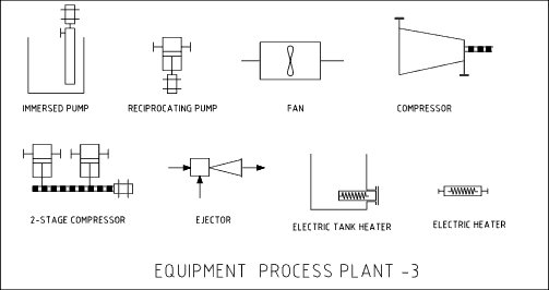
Symbols for Process Equipment.
The level of detail for the equipment relates to the type of schematic being produced. A Process Flow Sheet will only show the basic level of information sufficient to show the essential process flow paths. An Engineering Line Diagram of P & ID drawing will show a much more detailed representation.
Process plant equipment symbols. Plant 1.
Process plant equipment symbols - Plant 2
Process plant equipment symbols - Plant 3
Symbols for line tagging and equipment identification.
Reading pneumatic symbols.
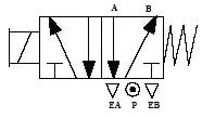
5/2 way valve with 5 ports and 2 position (conditions)

The block symbolises the possible valve function. Example a 5/2 valve schematic with 2 blocks describing the two possible valve functions or positions. A 5/3 valve schematic will show three blocks describing the three possible valve functions.

Pneumatic or fluid valves can be operated in several ways. Hand operated including levers, push and or pull buttons, air or fluid pilot operated remotely or internally by pneumatic or fluid pressure signals or solenoid actuated directly by electrical signal

The inverted triangle symbol denotes an exhaust port. The letters EA indicate an exhaust port for the A circuit, and EB denotes exhaust port for B circuit.
The arrow symbol denotes the flow direction of gas or liquid media into and out of the valve ports.. Pressure or inlet from port P. Depending on which on which of the valve blocks is in function the gas or liquid media flow is directed to port A or port B accordingly. A line with an arrow on each end denotes ability to control flow in both directions.
The spring symbol defines the AT REST position of the valve. The spring pushes from the side that is in drawn on and will return the valve to its failsafe position unless actuated otherwise.

The T symbol indicated that this port is closed and is neither passing or exhausting any media.

The P symbol denotes the air or liquid media pressure inlet or the number 1 can also indicate inlet port.
| Measured Variable | Type of Conditioner | Type of Component |
|---|---|---|
| F = Flow | R = Recorder | T = Transmitter |
| L = Level | I = Indicator | M = Modifier |
| P = Pressure | C = Controller | E = Element |
| Q = Quantity | A = Alarm | |
| T = Temperature | ||